by Michael Tyler of CarveBuddy.com
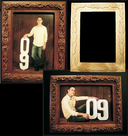
This article will show you how easy it is to create a basic one-piece picture frame with your CarveWright System.
The process is fairly simple and employs the Drawing tools as well as the Surface and Merge tools in the Designer software. In a few minutes, you can create your own custom frame in Designer. I outline the steps for creating a frame for a standard 5” x 7” photograph, but you can customize your own frame to whatever dimensions you wish. You can also download the completed ready-to-carve file (zipped mpc file) here:
STEP 1
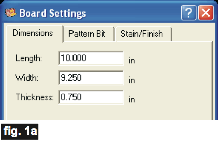
Start your designer software and create a new project with a virtual board that measures .75”x9.25”x10”. (fig. 1a)
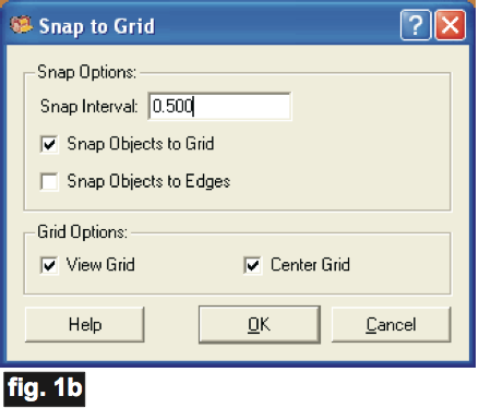
Turn off the board texture (View/Toggle Texture), then turn on the Layout Grid (Layout/Snap) and make the following settings. (fig. 1b)
STEP 2
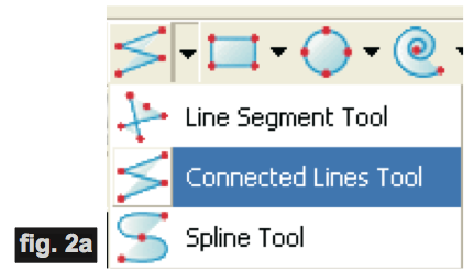
Activate your Connected Lines Tool from the line drawing menu dropdown selection. (fig.2a)
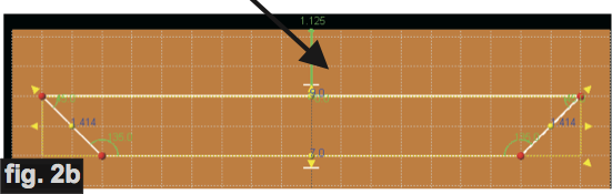
Draw a horizontal mitered corner shape for the long side of the frame by clicking on the board to place your lines. The grid will snap your lines into position. Make sure that the lines are connected by observing when the cursor makes a red “starburst”. The shape should be 9” long at the top and 1” tall. (fig. 2b)
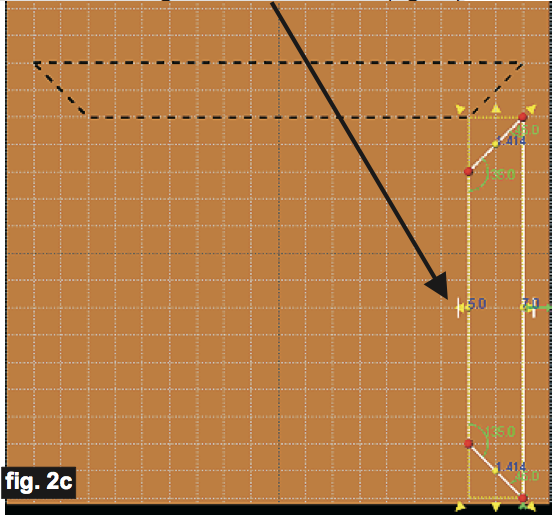
Draw a vertical mitered shape for the short side of the frame, measuring 7” tall and 1” wide. (fig. 2c)
STEP 3
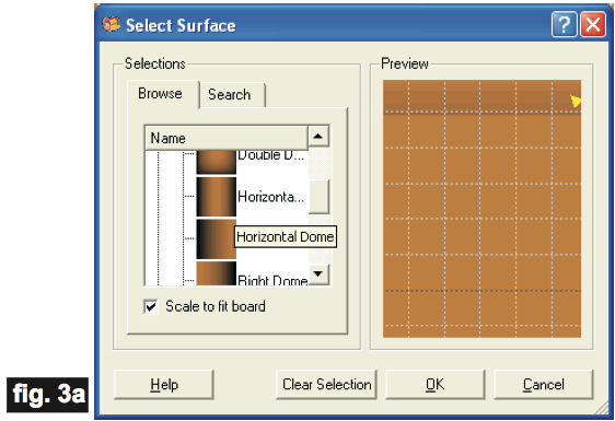
Select the top mitered shape. Using the Select Surface Tool, assign a Vertical Dome Surface. Now, select the side mitered shape and assign a Horizontal Dome Surface. (fig. 3a)
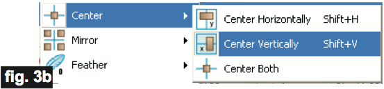
Right-click the side shape and select Center/Center Vertically. Similarly, select the top shape, right-click and select Center/Center Horizontally. (fig. 3b)
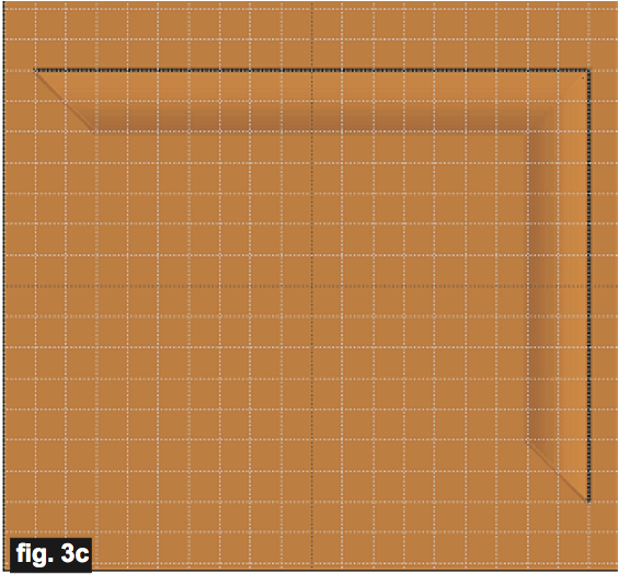
Your board should now look like this (fig. 3c).
STEP 4
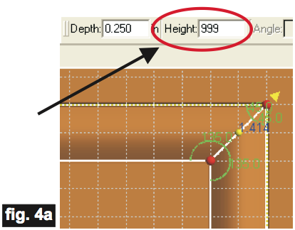
Let’s give the domed surfaces a little more “rise” by selecting each shape and typing “999” in the Height Box. (fig. 4a)
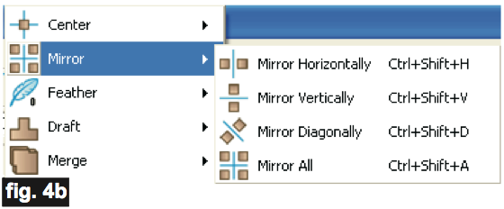
Right-click the side shape and select Mirror/Horizontally. Right-click the top shape and select Mirror/Vertically. (fig. 4b)
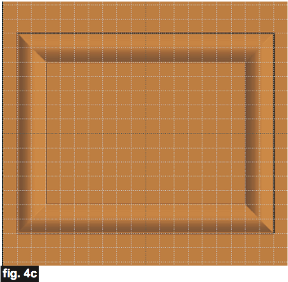
Your board will look like this (fig. 4c)
STEP 5
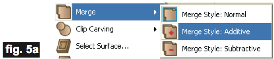
Turn off the Snap (Layout/Snap/Snap Objects to Grid – to remove the checkmark). Drag some ornamental patterns from your Basic pattern library onto the frame pieces and stretch/reduce/rotate to fit. I used the Corner01 and the FilagreeFlower01. Remove the “feather” and right-click each decoration, then select Merge/Merge Style: Additive for each. This allows the pattern to conform to the frame’s dome curvature. (fig. 5a)
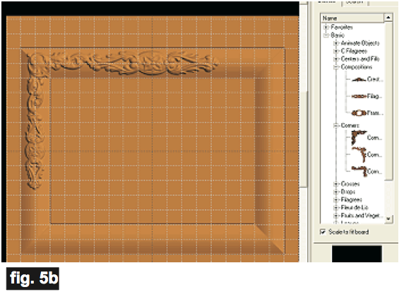
Your board will look something like this (fig. 5b)
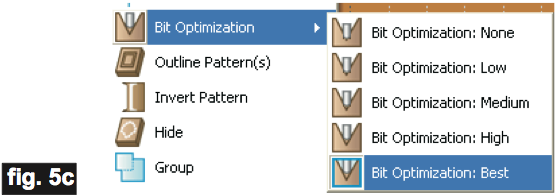
Right-click each decoration and select Bit Optimization: Bit Optimization Best. (fig. 5c)
STEP 6
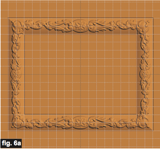
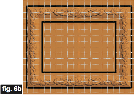
Select the decorative patterns and mirror them to fill the remaining part of the frame – use mirror vertical, horizontal, and mirror all (the corners) wherever it is appropriate. Your board will look like this (fig. 6a).
Select the Rectangle Tool and draw a 7”x5” rectangle, then use Center Both to place it dead center. Make this rectangle a Carve Region with a depth of .25”.
Draw another rectangle that measures 6.5” x 4.5”, center it, and click the Cut Path tool to make it a cut path (do NOT flip path).
Draw the final front rectangle that measures 9” x 7”, center it, click the Cut Path tool to make this the outer cutout path. You DO want to use the flip cut option on this cut path! Your frame should now look like this (fig. 6b). This completes the front of the frame.
STEP 7

Click the Rear View button “R” to flip the board over to view the backside of the frame. (fig. 7a)
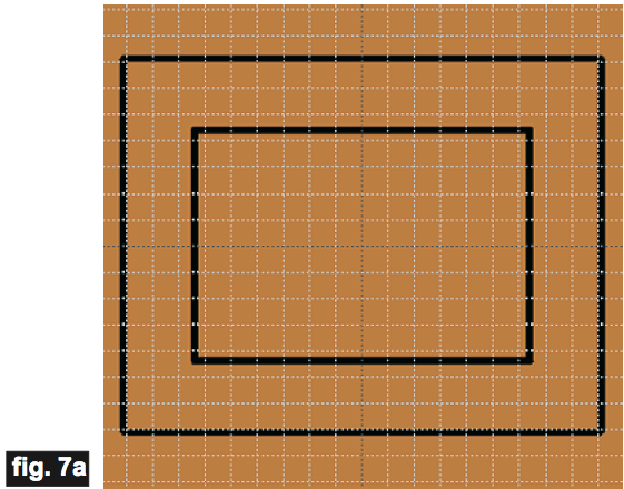
Draw a rectangle that measures 7” x 5”, center it, then make this a Carve Region with a depth of .2”.
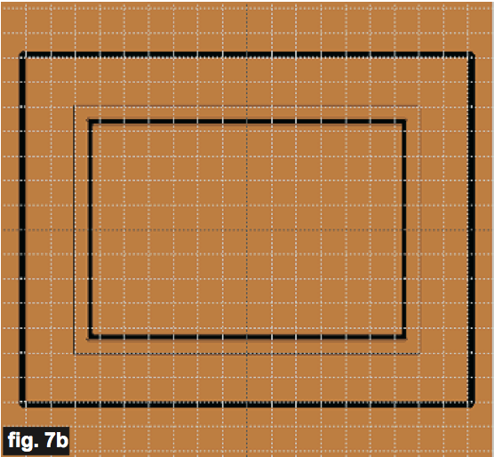
NOTE: You can alter this depth to match the thickness of the glass, photo, and any photo backer cardboard for your particular photo.
The back should look something like this (fig. 7b)
This completes the layout for the entire frame. You may now save your project and upload it to your memory card at any time.
Carving the Frame Project
STEP 1
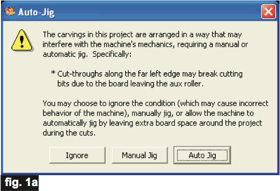
All you need to do at this point is upload the project file to your memory card. (File/Upload). When you upload, you may or may not get a pop-up window with an “Auto-Jig” warning message (Fig. 1a)
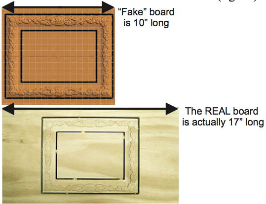
The picture frame is laid out on the software’s “virtual” board so that it just fits within the virtual board’s area. The real board you will put into your machine needs to be at least 7” LONGER than the “fake” board in the software. The frame’s “fake” board measures .75”x9.25”x10”. This requires that the real board you will use for this project will actually measure at least .75”x9.25”x17”. It is always best to run projects under the rollers to avoid any problems. It is an absolute requirement that any project that has cut outs (like this one), MUST remain under the rollers at all times. A minimum of 31⁄2” is added at each end of the real board in order to assure that. (fig. 1b)
If you do see the Auto-Jig message, you may safely click on “Ignore” because our actual board will be long enough that it won’t cause any problems at all as long as you have added at least 7” to the length. After the project is compiled, select “Best” or “Optimum” for the File Quality setting.
Click “OK” and upload the mpc (project file) to your memory card. Insert the card into your machine and load a board that measures the appropriate dimension for your particular mpc. If you have never run a two- sided carve project before, it is a little different than single-sided projects. The BACK of the board is always done first! Follow the prompts on your machine’s LCD carefully. I have outlined the steps for you in Step 2 (using the example mpc) below…
STEP 2
You will see “Project Menu” on your LCD display. Press “1” then scroll to the Basic5x7_Frame.mpc project, and press the green ENTER button to select it. Then follow the additional prompts….
- Stay Under Rollers – press 1) YES
- Press Enter to Proceed: Board (Back) – Press ENTER
- DO NOT RESIZE or SCALE the projects! If prompted, always keep the original size. No scaling!
- How to place on Board – press 1) Center On Length
- Cut Board to Size? – press 2) NO
- Select Carving Bit: 1/16” Carving – Press the green ENTER button. The machine will move the bit holder to the center of the machine in preparation for the bit installation.
- Load Bit:1/16” Carving – Insert your 1/16” carving bit, then press the green ENTER button. The machine will go through a series of homing steps and then proceed with the carving process for the BACK of the board. (The back carving is always performed first.)
- After it is done carving the back, you will be prompted to “Please Flip Piece”. Raise the head of the machine to remove the board.
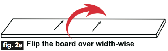
- Please Load Piece: Board – Brush off the board, clean excess sawdust debris from the machine and flip the board over width-wise, top-to-bottom (NOT end to end! see Fig. 2a). Put the board back into the machine (blank side up) and crank down the head.
- Press ENTER to Proceed (will measure board again)
- Select Cutting Bit: 1/8” Cutting – Press the green ENTER button. The machine will move the bit holder to the center of the machine in preparation for the cutting bit installation.
- Load Bit: 1/8” Cutting – Remove the 1/16” carving bit, clean the chuck and insert your 1/8” cutting bit, then press the green ENTER button. (homes, etc.)
- Select Carving Bit: 1/16” Carving – Press the green ENTER button. The machine will move the bit holder to the center of the machine in preparation for the bit installation.
- Load Bit:1/16” Carving – Remove the 1/8” Cutting Bit and insert your 1/16” carving bit, then press the green ENTER button. The machine will go through a series of homing steps and then proceed with the carving process for the FRONT of the board.
- After it is done carving, you will be prompted to load your 1/8” cutting bit. Take out the 1/16” carving bit, clean the chuck, load your 1/8” cutting bit, then press the green ENTER button. (Cutouts are always performed on the front of the board and occur last, after all raster carving is completed.)
- The machine will now proceed to make your cutouts as it moves around the outlines of every component. It leaves little tabs to hold each part in the board.
- When the machine is finished, remove your board. Turn off your machine – wait several seconds for the LCD to go blank, then remove your memory card.
CONCLUSION
Remove the frame from the board, then sand and finish your frame as you wish. It can be painted, stained, antiqued, gilded – whatever you like! Feel free to create your own variations of this project.
This project demonstrates a particularly handy software and machine feature…
On two-sided carves that have pre-carved regions on the backside of a project like this picture frame: The pre-carved area on the back occupies an area that will be cut out on the top-side of the piece (using the “smart” auto cut path feature). You might think this would cause a problem since the board thickness does not extend all the way down to the base (due to the carve region). Not so! The machine software is “smart”!
In this example, the MPC contains both the data for the back and the front of the board so that this “smart” feature will work correctly for auto cut paths. It will compensate for the removed material and calculate accordingly for the safety tab placement.
The software “knows” that there are pre-carved areas on the backside and places the tabs where wood still exists – all automatically!
It is important to run a two-sided project like this all at once as a single mpc. You should NOT divide a two- sided project into 2 separate mpc’s if there are any carve regions on the backside, along with auto-cutpaths on the front. Doing so would prevent the machine/software from calculating for the missing material on the back. Remember, it is essential to run two-sided projects of this type as ONE mpc project.
I hope you have enjoyed this tutorial and have learned some new techniques that make your experience with your CarveWright System more fun!